
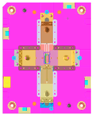
Mold Design Example 1
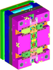
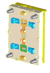
- component Overall size: 30 x 30 x 15 mm
- Material: PBT
- Number of Cavities: 2
- Type of Mold: Two plate with 6 Change overs
- Type of feed: Cold sprue, Submarine Gate
- Cooling Ckts: Plate Cooling
- Ejection: Ejector pins & blades
Critical features of the tool
- 6 Change over (versions)
- Four side cores were required for the product
- Due to side cores present on all the four sides of the component the feeding system was complex, a thorough analysis is made & gating position is made as per the customer requirement.
- 0.58mm dia slender side core pin is used for the hole formation in the component from the side cores which was having side core movement of 19.75mm & it is reduced to 4.0mm by advising the modification in the hinge profile of the component
Mold Design Example 2
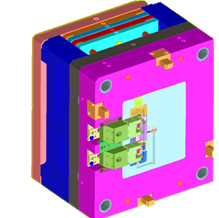
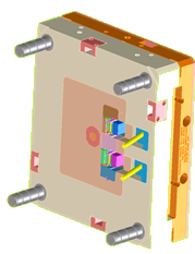
- component Overall size: 150 x 50 x 50 mm
- Material: PBT
- No Of Cavity: 01 & population to 2 cavity
- Type of Mold: Two plate with 3 Change overs
- Type of feed: Hot sprue, Submarine Gate
- Cooling Ckts: Plate, Housing, Insert Cooling
- Ejection: Flexi cores, Ejector pins & blades
Critical features of the tool
- 3 Change over (versions)
- Two side cores were required.
- Due to lob (undercut) portion present on the housing which is unable to form in the side cores, an additional technique called flexi cores are used to form these undercuts, Also an additional Double action ejection is designed for the ejection of the component once after the component releases from the flexi cores.
- Based on Mold flow analysis a thorough analysis has been made to minimize the warpage on the housing module & guiding plate locating leg portion during the design stage by providing warpage compensation
Mold Design Example 3

- Component Overall size: 70 x 50 x 50 mm
- Material: PBT
- No Of Cavity: 01
- Type of Mold: Two plate mold
- Type of feed: Hot Runner, Submarine Gate
- Cooling Ckts: Plate Cooling
- Ejection: Ejector pins & blades
Critical features of the tool
- Two components are molded by bridging the connecting rib & complex splitting of inserts
- Hot runner system with single dropper.
- Four side cores were required.
- Due to side cores present on all the four sides of the component the feeding system was complex i.e., runner system is designed on the side core insert, a thorough analysis is made & gating position is made as per the customer requirement.
- Based on Mold flow analysis a thorough analysis has been made to minimize the warpage on the housing module during the design stage by providing warpage compensation